Testing Standards and Insertion Loss Control for Fiber Optic Patch Cords
This article explores the key testing standards and methods used to control insertion loss in fiber optic patch cords, helping businesses ensure product quality and system efficiency.
2025-05
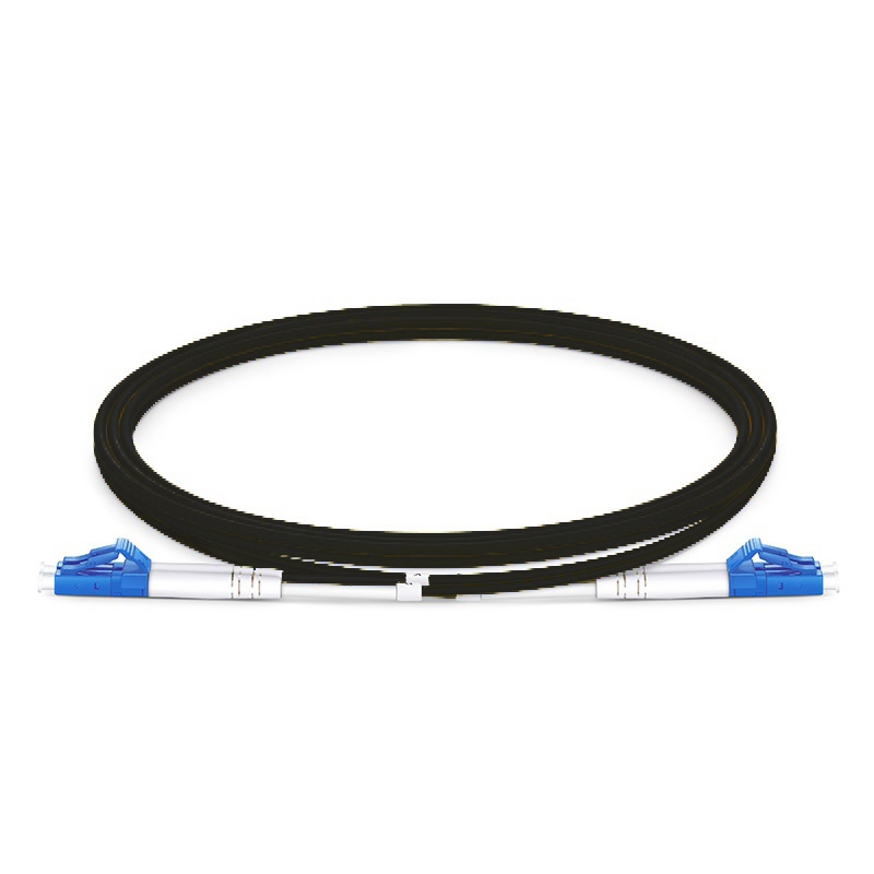
Fiber optic patch cords are critical components in modern communication networks, ensuring reliable and high-speed data transmission. As demand for bandwidth continues to grow, maintaining high performance and low loss in fiber connections has become more important than ever. This article explores the key testing standards and methods used to control insertion loss in fiber optic patch cords, helping businesses ensure product quality and system efficiency.
What Is Insertion Loss?
Insertion loss refers to the amount of optical power lost when a patch cord is inserted into a fiber optic link. It is measured in decibels (dB). Lower insertion loss indicates better signal transmission quality, which is essential in high-performance optical networks such as data centers, FTTx systems, and telecommunications infrastructures.
Industry Testing Standards for Fiber Optic Patch Cords
To guarantee quality and consistency, fiber optic patch cords are tested according to several international and industry standards:
IEC 61300 Series: Provides standardized test methods for fiber optic interconnects, including insertion loss and return loss testing.
TIA/EIA-568.3-D: Outlines minimum performance requirements for optical fiber connectors, including multimode and single-mode patch cords.
ISO/IEC 11801: Specifies cabling standards for generic cabling systems, relevant to data center and enterprise networks.
Telcordia GR-326-CORE: Widely used in North America for single-mode patch cord qualification, specifying mechanical and optical performance requirements.
Insertion Loss Control Techniques
Controlling insertion loss begins with high-quality materials and continues through every stage of production and testing:
1. Connector Polishing
Precise polishing of connector end faces is crucial. APC (Angled Physical Contact) and UPC (Ultra Physical Contact) polishing types help minimize back reflection and insertion loss.
2. End Face Inspection
Using interferometers and automated inspection tools ensures that end face geometry meets required standards, including radius of curvature, apex offset, and fiber height.
3. 3D Testing
Advanced 3D interferometry can detect microscopic defects and irregularities on the connector surface, which can significantly affect insertion loss.
4. Insertion Loss Testing
Performed with a light source and power meter or an Optical Loss Test Set (OLTS). Testing is conducted under both single-mode and multimode conditions based on product type.
5. Quality Control and Traceability
Barcoding and digital traceability systems help maintain consistent production quality and ensure compliance with customer and industry requirements.
Typical Insertion Loss Values
| Connector Type | Insertion Loss (Typical) |
|---|---|
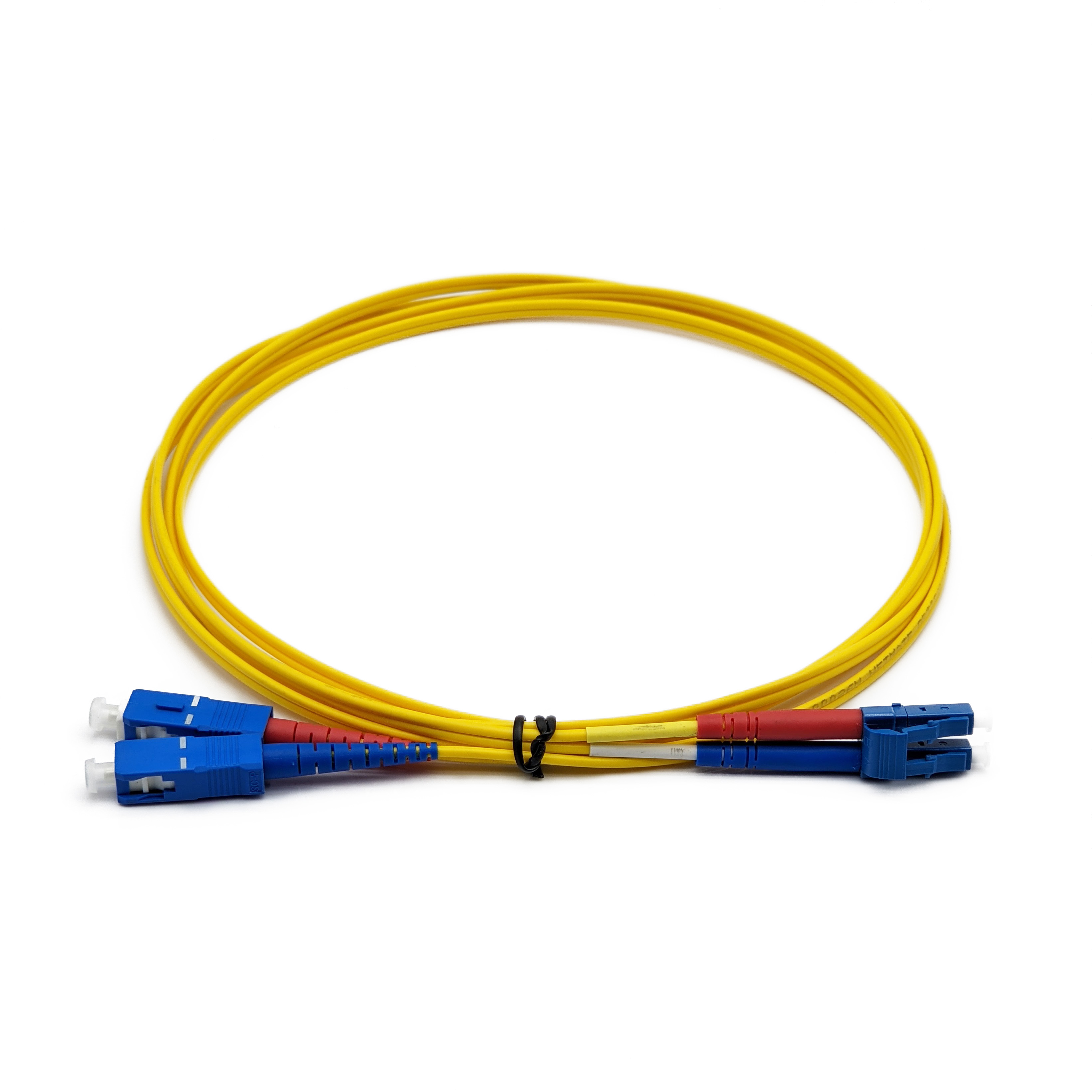
| SC/UPC | ≤ 0.2 dB |
| SC/APC | ≤ 0.3 dB |
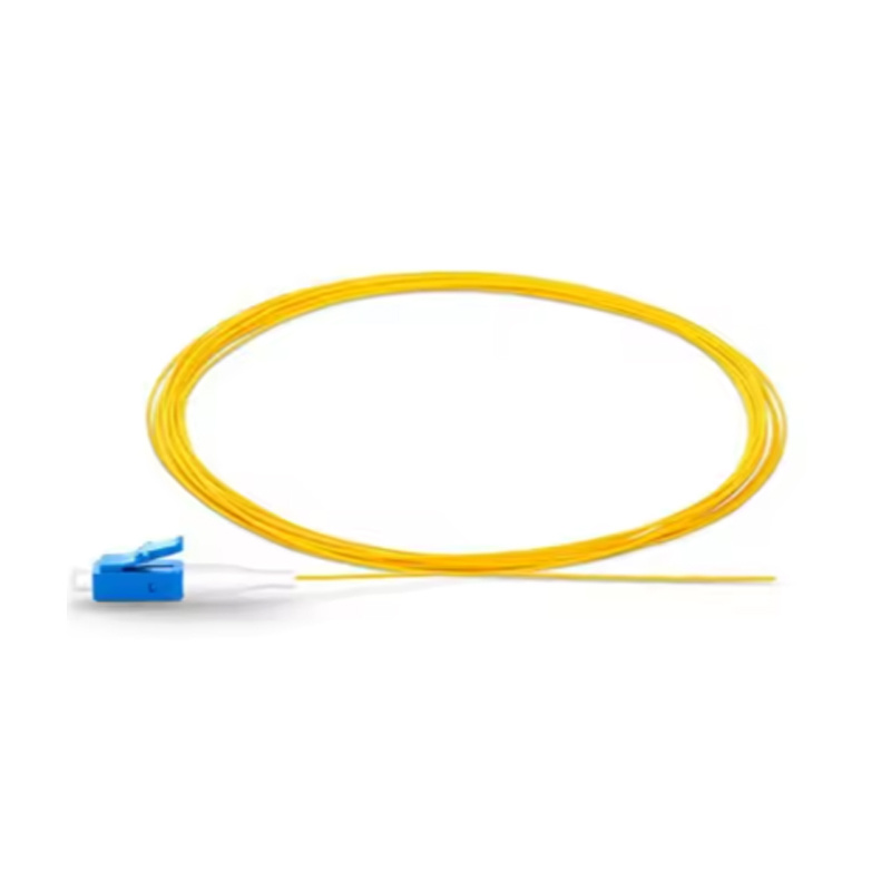
| LC/UPC | ≤ 0.2 dB |
| LC/APC | ≤ 0.3 dB |
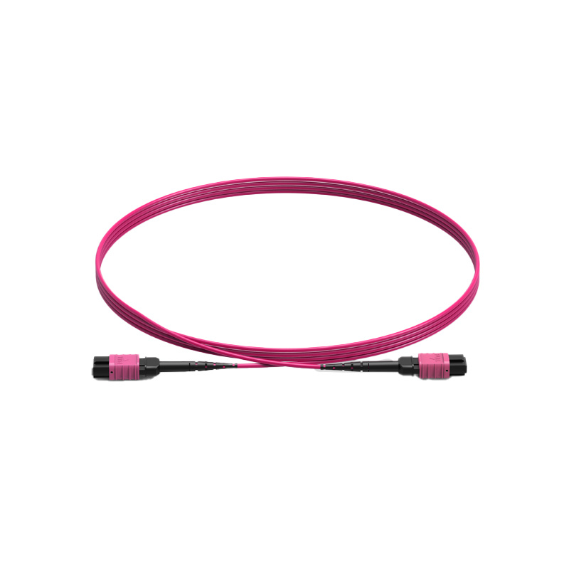
| MPO/MTP | ≤ 0.35 dB (Elite) |
Note: Actual insertion loss may vary depending on fiber mode (single-mode vs. multimode), connector type, and assembly quality.
Conclusion
Reliable fiber optic patch cords are the foundation of efficient optical communication systems. Strict adherence to international testing standards and precise insertion loss control can significantly enhance system performance and customer satisfaction. Manufacturers who invest in high-quality materials, automated inspection, and advanced testing equipment can set themselves apart in a competitive market.
Related News
CES in the United States(Date: January, 2024&January, 2025)
CES is the world's largest consumer electronics show, Major product trends include AI, IoT, automotive technology, AR/VR, robotics, autonomous driving, sports technology, etc.
IEAE Exhibition in Russia(Date: August,2024)
IEAE Exhibition in St. Petersburg,Russia, the booth No.: F.B15
Sorry,当前栏目暂无内容!
您可以查看其他栏目或返回 首页
Sorry,The current column has no content!
You can view other columns or return Home
COOKIES
Our website uses cookies and similar technologies to personalize the advertising shown to you and to help you get the best experience on our website. For more information, see our Privacy & Cookie Policy
COOKIES
Our website uses cookies and similar technologies to personalize the advertising shown to you and to help you get the best experience on our website. For more information, see our Privacy & Cookie Policy
These cookies are necessary for basic functions such as payment. Standard cookies cannot be turned off and do not store any of your information.
These cookies collect information, such as how many people are using our site or which pages are popular, to help us improve the customer experience. Turning these cookies off will mean we can't collect information to improve your experience.
These cookies enable the website to provide enhanced functionality and personalization. They may be set by us or by third-party providers whose services we have added to our pages. If you do not allow these cookies, some or all of these services may not function properly.
These cookies help us understand what you are interested in so that we can show you relevant advertising on other websites. Turning these cookies off will mean we are unable to show you any personalized advertising.

